


Pipe Jacking
Closed Shield
Pipe jacking enables the construction of sewers and pipelines with minimal disruption, for example, in inner-city traffic routes. Compared to open-cut installation, traffic disruptions can be reduced, which can also lower traffic-related emissions.
Since this method requires the removal of only the soil displaced by the new pipeline, this innovative construction method can significantly reduce construction site traffic compared to conventional open trench / open cut construction and also conserve resources, as very few external construction materials need to be delivered.
These methods enable highly precise pipeline installation over long distances using state-of-the-art electronic measurement techniques. The diameter ranges in pipe jacking start at the lower end of the range used in mechanical tunnel boring with tubbing lining. Existing software solutions make it possible to provide the client with real-time, online access to all relevant data regarding the tunneling process.
Procedure Description
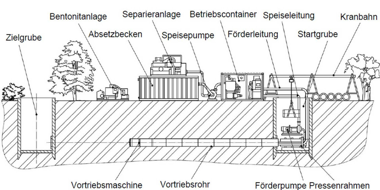
Source: DWA-A 125 (Figure 11)
The tunneling pipes are driven from a launch pit to a target point—usually a target excavation pit—while the pipe string is continuously jacking forward. At the same time, the soil is continuously excavated at the mechanically and hydraulically supported working face. The material is conveyed using a slurry, which is processed by a Mud rig in the area of the launch pit and returned to the conveying circuit. The process is controlled via control cylinders in the drill head, enabling advance in a straight line or around curves.
Application Criteria
Microtunneling, Section 6.1.3.1, and Shield Tunneling, Sections 6.2.3.5 and 6.2.3.6
> 1.000 m
Vertical, horizontal, and spatial curves are possible; radii depend on pipe diameter and geology; R ≥ 150 m
Reinforced concrete, polymer concrete, fiberglass-reinforced plastic, stoneware
For sewer lines
| DN | vertikal | horizontal |
| < 600 | +/- 20 | +/- 25 |
| > 600 bis < 1000 | +/- 25 | +/- 40 |
| > 1000 bis < 1400 | +/- 30 | +/- 100 |
| > 1400 | +/- 50 | +/- 200 |
Source: DWA-A 125 (Table 10)
With this system, obstacles made of steel or reinforced concrete can only be removed by taking additional measures.
In all soils that have the required bearing capacity, including bedrock up to 200 MPa
Sewage lines, protective pipes, utility tunnels
Crossing rivers, roads, highways, wetlands, open areas, cuts in the terrain, narrow passages, and numerous intersecting lines.
Current
News
Information and news from the various business divisions of the Max Bögl Group. Read the latest articles about our services, Technologies, and what we’re doing.


